A poster on OGR has begun the Stevenson NYC 0-6-0. Photos indicate that he is doing nice work, and that the kit is comprised of some really nice etchings and castings. I noted his post this AM - I can still look at OGR posts, although they expressed interest in blocking even that.
Funny - I was just thinking of Bob Stevenson last night as I attached his injectors and check valves to my now semi-attractive SP SE-4. I had decided to shoot him an e-mail this AM - he has endured a few health challenges as of late.
Well, as you might guess, I have some of the answers the poster requested, but am unable to post where he can find them. And it is sort of hopeless that we could add him here as a participant. We couldn't get "Strummer" added - we tried.
My Stevenson writeup is over 11 pages, not counting the decals I created for the project. Alas, no NYC decals, but enough SP decals to keep the average modeler busy for a decade! I suppose I could post all 11 pages here, but not sure how the forum structure would handle so much text - and not at all sure the average forumite would care to read it all.
So, not wanting my e-mail available publicly (I get plenty of spam already, and absolutely hate right wing "send to all" stuff) I may be able to provide copies through Mark, or some other person not quite so protective of their e-mail.
For now, let me get a few Stevenson photos posted here, since this forum needs a few pictures to bring us back to modeling. No darts thrown at that printed boxcar; I am totally impressed by the results, and stunned that anyone has the time to input all that data. Does the computer actually look at the prototype photo for rivet strips, or do they have to be dimensioned and specified each and every time? Can you imagine a locomotive frame casting done to the same standards, or even some truck side frames? In lost-plastic bronze or brass, of course!
Stevenson 0-6-0
-
bob turner
- Posts: 12847
- Joined: Sat Jan 13, 2007 7:57 pm
Re: Stevenson 0-6-0
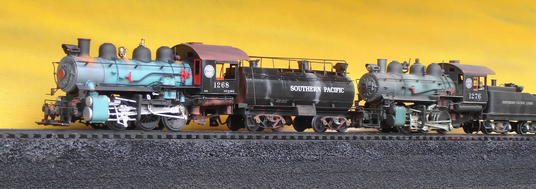
You have seen these before - here is the finished Stevenson model, in front, trailed by a 1950 Lobaugh version:
Right side portrait:
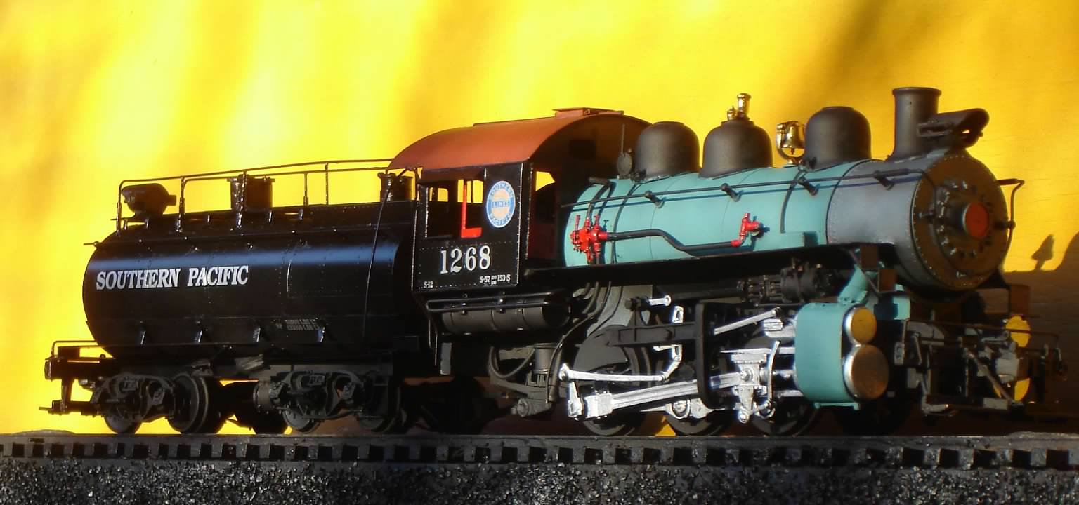
Right side portrait:
-
bob turner
- Posts: 12847
- Joined: Sat Jan 13, 2007 7:57 pm
Re: Stevenson 0-6-0
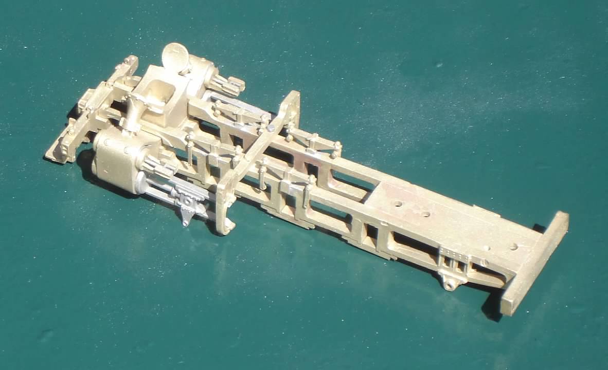
This is what Bob created to replace the sand cast Lobaugh frame - I consider this a work of art, and possibly the best locomotive bed casting ever done in O Scale. Just think of what could be done with that 3D printer! I would not be averse to building another SP Mountain or Mike if somehow a frame like this became available.
-
Rufus T. Firefly
- Posts: 41330
- Joined: Wed May 16, 2007 6:52 am
- Location: Departed from this forum
Re: Stevenson 0-6-0
bob turner wrote:Well, as you might guess, I have some of the answers the poster requested, but am unable to post where he can find them.
What's wrong with posting them here? Anyone can see everything here w/o logging in or joining.
You could also just directly email Norton. Check your email....
Conservatism: The intense fear that somewhere, somehow, someone you think is inferior is being treated as your equal.
-
bob turner
- Posts: 12847
- Joined: Sat Jan 13, 2007 7:57 pm
Re: Stevenson 0-6-0
Happy to do both.
I will let you take a look first.
I will let you take a look first.
-
bob turner
- Posts: 12847
- Joined: Sat Jan 13, 2007 7:57 pm
Re: Stevenson 0-6-0
P S - two requests to post here, not including Martin above.
I will try to post it all at once - if the machine chokes, I will divide it up.
Please don't waste time reading if this sort of thing does not interest you - I am not trying to bore anybody.
I will try to post it all at once - if the machine chokes, I will divide it up.
Please don't waste time reading if this sort of thing does not interest you - I am not trying to bore anybody.
-
bob turner
- Posts: 12847
- Joined: Sat Jan 13, 2007 7:57 pm
Re: Stevenson 0-6-0
Okay - hold your breath: Posting!
-
bob turner
- Posts: 12847
- Joined: Sat Jan 13, 2007 7:57 pm
Re: Stevenson 0-6-0
The Stevenson SP 0-6-0 by Bob Turner
July 13, 2010
Bob Stevenson always has a series of unfinished kits on his table at shows, so I volunteered to build a Harriman 0-6-0 up for him so he could have a finished, painted, running model to display. I am not altogether altruistic – this way I get to see his efforts and still stay within my own personal budget, which is pretty much limited these days. And besides, if the Harriman 0-6-0s are not my favorite prototype, they are pretty close.
Several things of interest before I start: First, just looking at Bob’s displays on his table is not enough even for experienced eyes to evaluate the quality of his products. This was not entirely obvious to me until I got the kit home, opened the box, and stared at the parts for a while. The only thing I saw at Bob’s table was that the drivers looked good enough to be Lobaugh, although they looked cleaned up a bit. Second, the Harriman 0-6-0s came in several flavors, and my personal favorite is the 51” drivered classes with 11’ wheelbases. The Lobaugh, and hence Stevenson, model is a rendering of the class S-12, which is a 57” drivered, 11’ wheelbase locomotive, although the right hand running board is found mostly on classes S-13 and 14. It is raised about eight inches above the cab floor, and thus winds up at a different level at the smokebox. I have only found photos of S-12 # 1283 with this type of running board. Also of note is that all classes had at least four common types of tenders, all of which intrigue me. And among the smaller drivered classes, particularly S-8 and S-9, SP used slide valve cylinders. I note that Lobaugh cast iron drivers scale out to about 54”, while Stevenson drivers come in at just over 55 ½”. To me, that is a license – I can make any locomotive I want out of either the Lobaugh kit or the Stevenson kit, merely by changing cylinders and maybe valve gear. The cab on the S-12 is distinctive for its sharp radius where the side joins the roof, but that is a detail left for the truly obsessed. I really never noticed it before about two days ago. The Lobaugh and Stevenson kits model this feature of the S-12 (although I believe the Stevenson kit is slightly more accurate in contour). And finally, disclosure: I own four Lobaugh switchers of various flavors, and have four completely scratch built models of the same prototype, with plans for more someday.
So far, my impression is that this model is a step above the Lobaugh model. It is not often that I would say such a thing, since I happen to like the bronze machined Lobaugh frame, but this frame is probably stronger than the original machined frame, perhaps as accurate in a dimensional sense, and surely way, way better looking. So far, I am going to guess that this model may well attain the status of the venerated Lobaugh “lost-wax” Mikado. I could write an entire feature about that one, but suffice to say that there are a very few out there, and those that exist are as good as they get. In fact, I was just looking at the new Glacier Park version of the SP Mike, and in a lot of ways the Lobaugh is much better, particularly in and around that neat Hodges trailing truck – but I digress. Stevenson Preservation Models brought to market a revised version of the Mikado, which uses the same castings and is quite nice, but it will not shoulder the original out of the way. This switcher may well replace the original Lobaugh 0-6-0 as the standard in very much the same way the 1950 Lost Wax Mike replaced the pre-war Lobaugh effort. That is, a well done Stevenson 0-6-0 may well increase in value over the years.
I was just going to look at the parts, then think about it for a while. I was so intrigued that in three evenings, I had the frame pretty much completed. The joke is that I watch the News Hour while I do these things, but it is true – why bother watching them talk, when one can listen and drill holes at the same time. So in short, a main frame with cylinders attached took about four leisurely hours. The main frame is a robust lost wax casting of one piece, with all holes drilled and most tapped – see figure 1. The pedestal binders were on a sprue, so they had to be cleaned up a bit, then they were screwed on. Cylinders were trivial, except that they need to be held with the piston and valve chamber inserts in place using a clamp during soldering, which I did with a torch. I only found three flaws in the frame parts: First, a screw hole for the crosshead guide yoke was slightly mis-placed – that was fixed in short order with a soldered-in insert. Second, the lost wax cylinder block was slightly “off” on the left side. I clamped it in a vice, and with a Crescent wrench I applied a tad bit of force, moving it into total and perfect alignment. And finally, when attaching the footboard pilot, I had to enlarge one hole a bit for frame alignment. This last was strictly a cosmetic fix, but I wanted it to look good.
Fitting driving boxes, pedestal binders, and coil springs must be done with some care, but it is straightforward. After I was all done, I chose to immobilize all driving boxes with shaft Loctite, at about the ¼ point, done by bolting the sprung and drivered mechanism to a surface plate – a very flat piece of aluminum. This takes some work, but it eliminates having to match springs and get each pedestal binder to hold the driving box at exact level. The goal for me is to have all six drivers touching an absolutely level section of track; I normally do that on switchers by making them unsprung at the outset.
Bob has arranged the drive wheels so that they do not need special equipment or even special talent to install. He apparently had a helper who was not careful, so there may be some drivers out there that will give problems. I will explain how to detect them.
The drivers are keyed British style, with square axle ends and broached holes in the axle hub. This seems to be a reasonable way to make a kit handleable for a novice modeler. All you do is clean off the flash on the back side of the driver and push it on the axle. A socket head screw then holds it on. The socket head screw looks like an axle with a bored center hole. All I can say is "I approve" - even though I prefer press fits and round axle ends. Most modelers would not like the press fit axles - too difficult to quarter.
You absolutely need to have all crankpins equidistant from the axle center. Measure it before you proceed much further than putting drivers on axles. They should all be within .010 of each other. Just use a caliper, and measure from outside the crankpin to the opposite side of the driver socket head axle screw. Also, you need all drivers in gauge, and not wobbling. If they are not in gauge, check to make sure the axle was machined properly – I had one that was cut too wide. Wobble is almost always due to improper tire installation – you can fix that with gentle pressure on the tire where it is not on the wheel perfectly. Wobble of a couple thousandths is acceptable, so long as the driver checks in gauge all the way around. I did have several drivers that were “off” in that the crankpin distance was too varied, but Bob replaced them with instant USPS shipment.
These are gorgeous drivers; the patterns were by Pacific Locomotive Works (no, not me, although I did have decals made in the 1980s with that name). The machining operation is fairly critical, so you may find a driver or two machined off-center. So long as the crankpin distance is within tolerance, an off-center driver will work just fine. It is an appearance issue, and with some black paint you will not see it. I suspect that perfect machining would drive the cost of this kit bonkers, since each of these parts is individually machined and pressed. But make sure you have a set that is within tolerance for good operation and reasonable appearance. Figure 2 will give you a good idea of how these drivers and rods will look before painting.
Side rods are drilled precisely at the dimension of the axle centers. That is, you install all drivers in the frame, exactly where they will go when you are finished, and measure center distances with a pair of dividers. Measure three times and drill once, please. You will have no problems finding the axle centers, since the socket head screws are centered in the axles. Then, if the pins are as above (that is, all within .010), you can slide the side rod on at back dead center, then rotate the driver pair to front dead center, and feel no binding.
You do one side rod at a time - always checking front dead center and back dead center.
That is true no matter how many drivers there are - here, the front driver gets an articulated rod that needs no drilling - just some diligent filing in the area of the clevis, or knuckle. Do not stop filing the clevis area until you are sure the pin and rod slide through FDC and BDC. I soldered mine, after making it smaller to fit and to match photos of the real rods. I then drilled, cleaned the solder out of there, and now have a nice clevised set of rods.
On one side the drivers had crankpins within .008. The other side drivers had only .001 variance pin-to-pin. There will be no binding, period, unless the quartering is off, and that is highly unlikely with the square end axles.
Now let me list all the places where you can have side rod problems. This list is something you need, no matter what steam model you are working on. I find these sorts of problems in almost any kind of steam model, including brass imports. First, if you do not do the FDC and BDC tests, you are doomed to failure at the outset. Next, look for counterweights and driver center bosses that contact the rods. (This particular model had an articulating clevis contacting the slightly elevated socket head axle screw on the center driver – probably took me a half hour to find it.) Then mount the cylinder and crosshead guide assembly, and look for clearance between rods and crosshead guides. Check the rearmost part of the guides for contact with the outside of that articulating clevis – I had that problem, and it took longer than a half hour to spot. Put the crossheads in the guides, and look for visible clearance. By the way, make sure the crossheads themselves slide almost loosely for their entire operational travel. I see a lot of crosshead binding in older models.
A couple of “impacts” took me a while to discover – the top of one of the side rod articulating clevises was hitting the upper crosshead guide. The rod itself hit the bottom of the yoke, and - surprise! - the oil cup on the center crankpin bearing hit the inner portion of both sides of the Walschaerts link mount. You have to get good at spotting these things.
You will have to trim the forward crankpin area of the side rods to clear – after all, this is a scale model with five foot gauge, too wide tread, and counterweights that extend outboard. All that adds up to clearance problems, so you will wind up sacrificing at least a quarter of the width of the forward crankpin bearing boss. The crankpin itself also gets trimmed so it is almost (but not quite) flush with the counterbore in the rod. Believe it or not, after I carefully trimmed the forward crankpin area, and immobilized the front driver bearings, I still had a clearance problem – difficult to fix after you have all the neat valve gear parts attached to the crosshead. So, take them down with a file so there is no question about contact with crossheads.
The mechanism at this point must roll on a piece of track with just a push. If it does not, find out why not and fix it.
Main rods are next – just slip them on and pin at the crosshead with an 0-80. Make sure the rod and pin do not extend inboard beyond the inner face of the crosshead. Then check again for smooth rolling. If there are no problems, you can then solder the eccentric cranks on the rear crankpins, holding the mains on permanently. Places to watch other than the forward crankpin include the center crankpin cap, which can and often will strike the rod and stop things. This is handled either with a spacer at the rear crankpin or by trimming the center crankpin area just as you had to do for the forward pins.
Once you get this far along, the valve gear and valve gear hanger will go on easily. Still, do it step by step, and watch for eccentric rods that strike the rear crankpin while rotating. Also, make sure that the bottom of each Walschaerts link is outboard of the main rod. Both of mine struck the main rod, and the only cure was bending the bottom of the link outward – a difficult trick, because the link is a tough nickel alloy. This, again, is due to the scale size of all components, coupled with wide gauge and wide driver tread. In retrospect, I should have (and could have) shaved off most of the inner portion of the clevis that attaches the eccentric rod to the Walschaerts link. Many O Scale models cure these sorts of problems by using cylinder blocks and valve gear hangers that have been widened to accommodate our 5’ gauge and .172” wheel treads. Others, such as MTH for one, simply make cylinders smaller and run the piston rods outboard of the center line. The cure, of course, is Proto-48.
Before mounting the motor and gearbox, make sure the entire mechanism rolls with just a gentle push from behind or in front. It should require no weight to get the drivers to roll through a full 360 degrees, and at no point should it have even a small “hitch in the getalong.” And remember, as you assemble the superstructure, check again for impacts. You could, for instance, mount the air pump too low and have a main rod strike. Sounds easy to find, but it can be baffling. See Figure 3 for the completed mechanism.
After getting the mechanism to an almost complete stage, I switched gears and started in on the tender.
The tender is one of my favorites – the sausage! I figured that I needed something a bit more substantial than the shell and base to clamp up for soldering, so I found some brass thick wall tube of 1 ¾” OD, and machined .020” off of the outer diameter for two pieces about an inch long each. I put them about where the trucks would mount, tinned the two water tank etchings, clamped with about four auto hose clamps of the spiral type, and heated gently with a torch. Magic: I now have a sturdy tank on which to build a tender. The underframe goes on easily – I mounted it slightly differently, since I had thick brass to drill and tap inside the water tank. A couple of flat head 2-56 screws hold it in place.
The oil tank goes on just about the way Bob Stevenson describes in his directions, but I took the time to drill and tap for a solid mount of the oil hatch, and used that to hold the tank in place while I gently soldered the tanks together. I just tinned the inside of the oil tank quite heavily, fluxed the water tank, checked three times for straightness, and heated gently with the torch.
The top walkway is a bit different – go ahead and cut the boards loose from the etching and move them lots closer together. Spacing can be made uniform with pins or nails in a piece of pine scrap. Tin the bottoms of the boards and then sweat the little spider web-like mounting etching to it. When bending the feet of that spider deal, use care – as Bob says, you only get one bend. Fit it to the water tank (note that the boards are too long, so you need to trim it to length) and make sure all the feet contact the side of the tank. Then heavily tin the feet (might want to put some solder in those fragile grooves, too), and then you are ready to solder the assembly to the water tank. My trick was to clean and flux the tank where the feet would go, then position and weight the walkway assembly with a brass bar – a heat sink as well as a weight. Very carefully heat the water tank near each foot until the solder just flows, then go on to the next foot. Never leave the flame in place long enough to get even the slightest discoloration in the brass.
Doing the lower running boards was interesting. The actual assembly is not covered well in the instructions, but the pieces are all in the kit. The rear platform can be carefully notched to slide up against the four handrail posts cast in to the footboard casting. Bob has included photos of the real thing, which give a hint as to what is going to happen. The front platform needs to be raised slightly – I attached the stirrup steps with 0-80 screws, which extend upward enough to make alignment and soldering of spacers easy. My spacers are K&S rectangular tube – 1/4x1/8 – and they solder easily without loosening any of the pre-soldered frame joints. Then you will note that the long running boards are slightly too long – just snip one of the short horizontal pieces off and make a butt joint on the top of the rear platform. There are lots of running board supports in the kit, but you need not install more than five per side to be prototypical. I installed four, and am hoping nobody will notice. They go on easily, by first forming them, then tinning all contacting surfaces. They go on the underside of the running board, so that the tiny feet rest upon the (cleaned and fluxed) tank. Then a rapid heat with the torch attaches the feet to the tank, right about at the edge of the lower shell. I had thought that heat would distort the rather timid running board material, but mine are dead-straight, with no real attention to heat distribution. Same deal with the tool boxes – tin everything, then heat the tool box with the 80-Watt. It gets hot quick; melts the solder on the running board, and you get out of there with the heat.
Upper handrails – the ones that form a walkway on top – are done in my inimitable fashion – except that it is really easy to imitate if you want. I use the smallest size of K&S tube, and solder a piece everywhere a vertical support goes. Then, when the time comes (last thing you do) you form the railings from brass wire, solder the uprights, and slide them into the K&S tube. They are best held with a non-permanent adhesive, so you can replace them when they get bent or broken. All of my tenders have this feature. I will deliver this tender with handrails slightly loose, so Bob can adjust them after shipment.
By the way, my rear platform is held on the casting with a pair of 0-80 screws, right where the casting is dimpled for handrail posts at the very outboard of the casting. I found that I could remove the 0-80s after the running boards were soldered and the rear coupler release bar was installed. At that point the platform is going nowhere – and I have holes for the transverse handrail that goes above the coupler cut bar.
I use Radio Shack 60-40 rosin core (readily available) and new flux. I recommend a Weller 80-Watt iron with a clean shiny tip. Others use more modern solders, and use a torch much more often than I, but I can tell you that I get good results, and have yet to use much tin-silver solder or a resistance soldering setup. Cleanliness is important, but if you get a new kit from Stevenson, most of the brass is just about ready for flux and soldering. I think he bright-dips all the parts.
The handrails and handrail posts that are about two thirds of the way up the tank are problematic, as are those on the locomotive boiler. I attempted to solder the cast posts on one side of the tender, and thought that it would be relatively easy with a torch. I wound up using the 80-Watt soldering iron, and then I wound up with lots of cleanup problems. The opposite side got two threaded Lobaugh posts, which enabled me to line up the other five cast posts with less than six hands. I thoroughly tinned the holes and the entire lower portion of each handrail post. The torch and a block of wood then made a very neat job of it. The locomotive boiler and smokebox front got all threaded posts – they are trivial to install; just drill and tap some scrap brass sheet with 0-80 threaded holes, and line it up in the handrail post hole before you try to insert the threaded post. You must use steel for any handrails that a torch will get close to, except for grab irons where you can keep the flame far from the skinny wire, and just heat the sheet metal. If a piece of brass wire ever gets red, pull it out, recycle it, and start over with new wire.
Tender trucks appear to be identical to the PSC SP tender trucks. The leaf springs are beautiful castings, and are apparently Ray Waller parts I chose to extend my leaf springs outward by about a 32nd, by inverting the assembly and drilling new holes to match the bolster. Also, I removed the inner bolster stud on each side, so that my two holes would fit the remaining studs and hold the upper spring leaf in place. It turns out that the assembly goes in quite easily if you install the coil spring first, then slide the leaf spring assembly in until it clicks. These things are indeed better looking than the PSC stamped springs. Measure carefully if you decide to drill new holes – the bolster stud pattern does not quite match the original pair of holes in the leaf.
I did not discover the trick of inserting the coil spring first until I was ¾ done – so I have weak springs, backed up with crescents of rubber hose. I probably will not go back and re-do that, since I still have equalization.
One thing to watch – if you drill the journal bearings too deep, the NWSL wheelsets may short out on the insulated side. If there is any question at all, put some insulating washers over the axle stubs on the insulated side before assembly. This one caught me during the track tests. Also watch for contact between insulated driver tires and almost everything. Mine shorted against the firebox sheet, and I was forced to glue an insulator on the firebox to match the driver.
--------------------------------
Boiler assembly requires some care – the cab and backhead get soldered in place, and they need to go on dead-straight. I built the entire cab, including doors and window mullions, before assembling the cab to the boiler, and I am rather glad I did – I cannot imagine trying to solder the cab wrapper to the forward bulkhead if that part were attached to the boiler first. The cab wrapper fits perfectly, but you will find that maybe a 64th of each bulkhead hangs below the wrapper. Take the time to trim that off before attaching the cab assembly to the boiler.
I made the mistake of soldering the backhead casting in place, with firebox sheets and cab floor boards soldered, before I realized that the motor will not fit inside that casting. I will be faced with trimming lots of brass out of the inside of the firebox with a Dremel tool and a face mask, before my motor fits. Do not make that mistake. Be sure the backhead casting has the firebox sheets removed, and be sure the boiler is cut open enough to clear the motor. That means opening it up all the way to where the throat sheet is soldered to the boiler – you can leave maybe a 32nd aft of where the throat sheet is to preserve solder strength.
The cab and backhead are best attached to the boiler by making a long rod, drilled at each end and tapped 2-56 or 0-80, depending on how big a hole you can tolerate in the backhead and in the smokebox front, and using the rod to hold the cab and backhead in place while you make sure both are dead-center on the domes and stack. I had my domes in place temporarily; I had soldered an insert in each dome, drilled and tapped 2-56, and used headless studs so I could drop them in place. They are now fastened permanently from inside the boiler with 2-56 socket head cap screws. I did the same with the stack, and used a small chunk of brass in the bottom of the smokebox for the mounting screw that comes up through the cylinder block. My small chunk of brass is an .032 hunk of brass tube, tinned but not soldered until the boiler was firmly attached front and back to the frame.
Some of the details could use a comment or two. I always use K&S tube for the injector to check valve lines, and always drill .032 holes in the injectors and check valves for stub wires to go in. Makes it easy to solder the heavy lines in place after the check valves are permanently soldered. The reverser probably goes under the right hand running board, since this model depicts an S-12 with the high running board on that side. Bob’s comment about reversers above the running board applies only to those 0-6-0s with lower running boards on the right – the ones even with the cab floor.
Visors over the cab windows really should be added, as should that conduit running down the middle of the cab roof. I did install the cab vent as a functioning door, because it was so easy to do so. Then I glued it shut! I hate things that flop open when a locomotive is inverted for maintenance. I spotted a photo of a well done model in Bob’s instruction sheet, and took the time to try to get mine almost as good. I don’t know why that model never made it to Bob’s display table, but it has features that are not in the instructions. The things that inspired me were the way the injector exhaust and rear sander tubes actually went down past the driver centers. I rarely model stuff like that, for operational reasons – but this time I made an exception. I did leave two features out: one was a curved rail between the cab rear and the cab overhang, the other was a rod that stiffens the steps at the front of the boiler running board.
I have suggested to Bob that he do boiler steps in lost wax, but I used the ones provided in the kit. If you drill a hole and pin the step to the side of the boiler, the soldering job is a lot easier, although not trivial. These steps and some of the tender spiderwork could use less deep fold lines, since breakage is more or less disastrous. I always confined bending to once, and filled each fold line with solder after bending. Bob has, as this was being written, cast up boiler steps that are lots easier to use.
Bob’s model was finished in green and black, with silver here and there, and a red cab roof. An SP shield was applied to the cab ahead of the window, and all doors, sashes, and fittings got a touch of flat insignia red. Figure 4 shows the completed and painted model – you can see the front part of an original Lobaugh S-12 on the right side of the photo.
I got the model in early July, and it made its first test run in mid-October. I am retired, but I do a lot of flight instruction and teach night school at a very small law college. I also have my own hobby to think of, and one very devoted customer who likes to get a locomotive now and then. But, do not think you will drop the box on the bench and have a finished locomotive in a week or so just because you are retired and have nothing else to work on – it will not happen. What will happen, though, if you take your time, is a prize-winning, accurate model. I do have misgivings about the drive system, since it is tight and constrained, with a tiny motor that rattles against the boiler and firebox sides. If it were my model, it would have been converted to the non-tower gearbox, and it would have an 8x24 Pittman in the tender. That would allow for a full firebox, no visual obstruction above the center driver, and a noiseless, powerful drive. I may, in the future, write exactly how to do that. I should mention, though, that Bob Stevenson assures me that this tiny motor is up to the task, and is quite rugged. I did not want to prove that for him, so stopped after a few successful circuits with a short freight train in tow.
The locomotive was nearing completion by January 2011. I found a giant source of noise inside the boiler – the rubber tube was contacting the firebox throat sheet, which was already 4/5ths gone. I snipped another 1/16” out of each side to clear, and also placed some card stock spacers to insulate the gearbox.
Epilogue – I indeed got it running fairly quietly, and it is now part of the Stevenson Collection and has been displayed at OSW and the Chicago March Meet 2011. Realizing that decals are no longer available at the corner drug store, I took the time to have my decal guy do some Southern Pacific decals. One sheet, for ten bucks plus postage, and you have enough to do twelve SP locomotives, if you do not mind the tenders having three different styles of the SOUTHERN PACIFIC lettering. We designed it so that one quarter of the sheet can be included in each kit, either Mikado or Switcher, and so the builder has a pretty good choice of road numbers without having to go through the work of piecing each individual number on the cab sides. We even include enough of the round SP logo to do eight locomotives per full sheet – or the nose of sixteen diesels!
-
bob turner
- Posts: 12847
- Joined: Sat Jan 13, 2007 7:57 pm
Re: Stevenson 0-6-0
If you made it this far, congratulations! Re-reading after 11 years leaves a couple places where I was not totally clear.
That decal sheet never made it into the kit itself, to my knowledge. It was last seen as part of the La Belle line of O Scale products, and I assume the owner still has the software. He has my permission to sell to anyone my products, which not only include this decal sheet, but also sheets for various passenger cars from Long Island to Sud Pacifico de Mexico, and freight cars including the Carnation reefer and the PRR Merchandise Box.
Our fellow forumite Maroon may have an Alps printer on line, and if he can get his hands on the software, maybe these things can again be printed for O Scalers.
Jim Wilhite was the owner of La Belle when I was doing my best modelwork. Antique airplanes all over the airport sport his decal legends for things like fuel quantity, "don't touch this knob" and checklists. I really miss his decal work. Our first deal was to reproduce the Baldwin 60000 legends as on that monster in the Franklin Institute in Philly.
-
J. S. Bach
- Posts: 5820
- Joined: Wed May 16, 2007 8:30 pm
Re: Stevenson 0-6-0
bob turner wrote:If you made it this far, congratulations! Re-reading after 11 years leaves a couple places where I was not totally clear. ...snip...
Thank you for posting that. Although I do not have an interest in building a locomotive kit (probably could not anyway; maybe not even an Athearn "blue box" kit
-
bob turner
- Posts: 12847
- Joined: Sat Jan 13, 2007 7:57 pm
Re: Stevenson 0-6-0
Thanks. I gave them to Bob, but retain the copyright. Anyone may use them or re-post them as long as they state "permission from Bob Turner, " or something like that with my name.
-
bob turner
- Posts: 12847
- Joined: Sat Jan 13, 2007 7:57 pm
Re: Stevenson 0-6-0
I agree that it is way too long, or wordy in the extreme.
I assume it would not be of use over on OGR - or perhaps it did get re-posted and immediately deleted by Arnold?
Or maybe possible re-posters are worried that they would get banished.
I assume it would not be of use over on OGR - or perhaps it did get re-posted and immediately deleted by Arnold?
Or maybe possible re-posters are worried that they would get banished.
Re: Stevenson 0-6-0
Bob,
I “know” the guy, I’ll relay this page to him.
Aaron
I “know” the guy, I’ll relay this page to him.
Aaron
Re: Stevenson 0-6-0
Hi Bob, Pete here, the guy building the Stevenson NYC 0-6-0. I only check this forum occasionally but have been a member for many years. I didn’t realize you were banned for OGR. Glad to hear you are well. Anyway, I will read your posts and give you an update, hopefully over the next few days.
Pete
Pete
-
bob turner
- Posts: 12847
- Joined: Sat Jan 13, 2007 7:57 pm
Re: Stevenson 0-6-0
Thanks. You are doing beautiful work. Post some photos here. We have higher resolution - but you need a "host."
Return to “O-Gauge, 2-Rail, Model Railroading”
Who is online
Users browsing this forum: No registered users and 10 guests