Flat Soldering Jig
Flat Soldering Jig
I need to layout and solder some brass cooling piping, as you would see on some steam engines. I have the piping and supports donated by the 3rd Rail NP Z5 I dismantled, but this steam engine layout is totally wrong. I'm trying to figure out a good way to hold the assembly while soldering it to the supports. Something flat that is heat resistant and capable of holding locating pins would be perfect.
-
Rufus T. Firefly

- Posts: 42157
- Joined: Wed May 16, 2007 7:52 am
- Location: To be Determined
Re: Flat Soldering Jig
Flat and heat resistant -- ceramic tile.
Holding everything in place -- several hemostats + weights.
Holding everything in place -- several hemostats + weights.
Invention, my dear friends, is 93% perspiration, 6% electricity, 4% evaporation, and 2% butterscotch ripple.
-
bob turner
- Posts: 13642
- Joined: Sat Jan 13, 2007 7:57 pm
Re: Flat Soldering Jig
This is indeed a problem area.
My solution is rectangles of .064 thick brass, drilled on one edge with holes to line up the little dowels. (we call them poles around here, but they are just wire, drawn straight).
All bending takes place prior to attaching to the running board. Planning ahead pays off, especially where cooling tubes double back more than once.
When all looks good, the running board is tinned both sides where the rectangular supports go, and they are sweat-soldered from above.
This obviously doesn't work when your running boards are safety tread or perforated. I will try to get a photo here, and will send UP a shot of said rectangles.
My solution is rectangles of .064 thick brass, drilled on one edge with holes to line up the little dowels. (we call them poles around here, but they are just wire, drawn straight).
All bending takes place prior to attaching to the running board. Planning ahead pays off, especially where cooling tubes double back more than once.
When all looks good, the running board is tinned both sides where the rectangular supports go, and they are sweat-soldered from above.
This obviously doesn't work when your running boards are safety tread or perforated. I will try to get a photo here, and will send UP a shot of said rectangles.
-
bob turner
- Posts: 13642
- Joined: Sat Jan 13, 2007 7:57 pm
Re: Flat Soldering Jig
This isn't my most complicated, and one of the hangers is crooked, but you get the idea. The most complicated, as I recall, was the NP Challenger - but the left side of the standard SP Mike is a close second.
Note that with a Dremel disc and a steady hand one can make the outside of each hanger look like the clamps on the real thing. Obviously, my method does not work at all when one is seeking total realism - the Lobaugh style hangers do that better - but like Butch, I really don't know how to hold the whole thing together while adding heat for just one more pole.
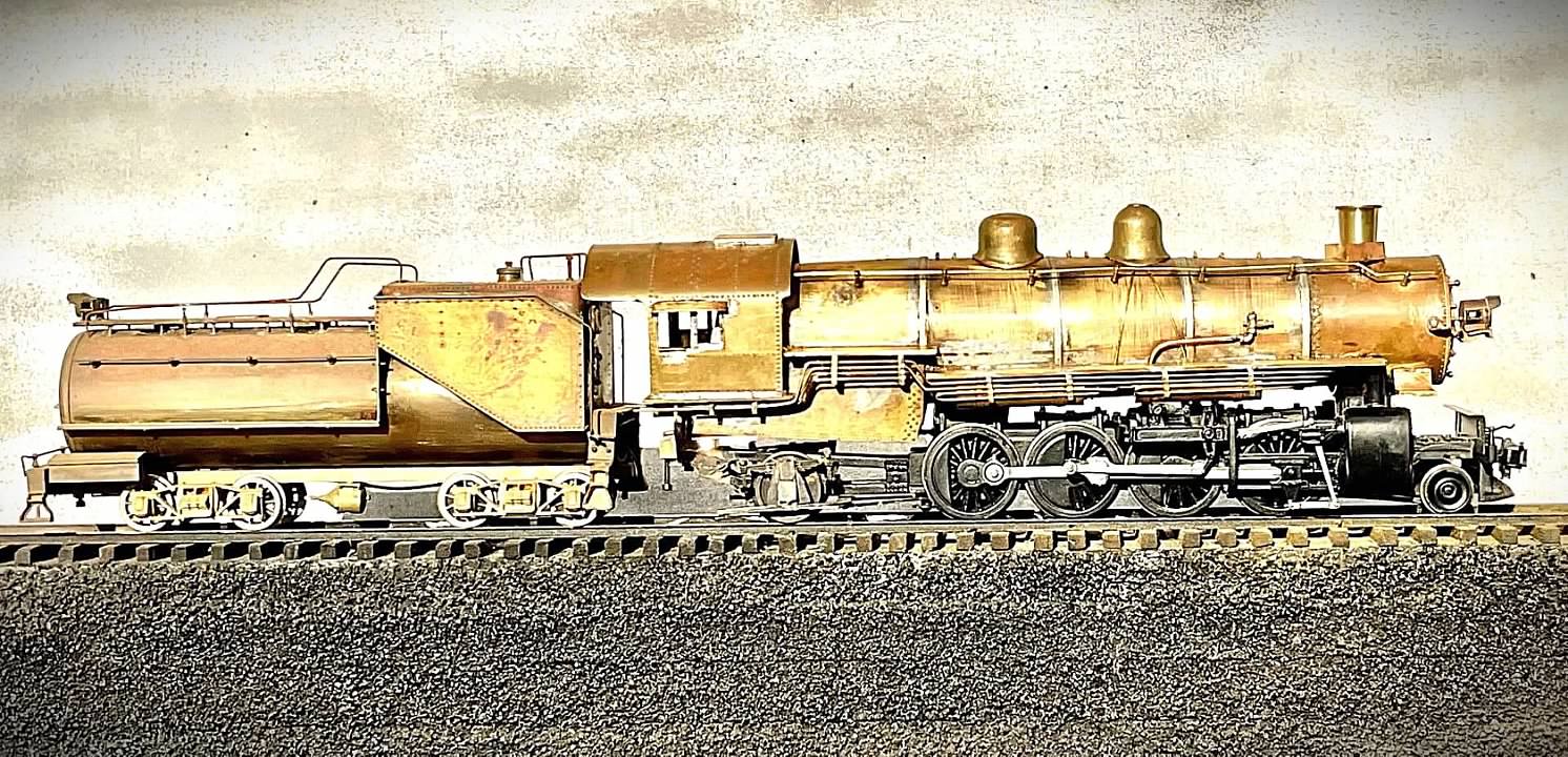
When I attempt to straighten that hanger over the rear driver, I will come on top with a well-tinned hot 80 Watt iron, and on bottom with a notched block of wood. Takes several seconds and done.
Note that with a Dremel disc and a steady hand one can make the outside of each hanger look like the clamps on the real thing. Obviously, my method does not work at all when one is seeking total realism - the Lobaugh style hangers do that better - but like Butch, I really don't know how to hold the whole thing together while adding heat for just one more pole.
When I attempt to straighten that hanger over the rear driver, I will come on top with a well-tinned hot 80 Watt iron, and on bottom with a notched block of wood. Takes several seconds and done.
-
bob turner
- Posts: 13642
- Joined: Sat Jan 13, 2007 7:57 pm
Re: Flat Soldering Jig
Yeah, here: This one is scratchbuilt with an Adams tender and PSC trucks. But what I am trying to highlight is that stack of tubes above driver #1. I have in the past scalloped the hangers with a Dremel, but as you can see, for just a standard model it really isn't necessary.
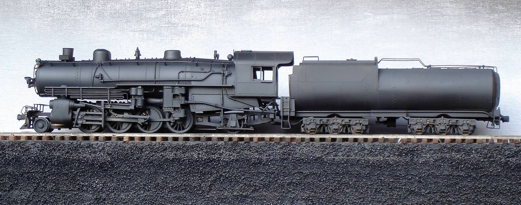
It does need the red touches on checks, injectors, and window frames. I'll go do that now.
It does need the red touches on checks, injectors, and window frames. I'll go do that now.
Re: Flat Soldering Jig
Good idea Martin I have a ceramic blocks that I forgot about. Bob your cooling pipe modeling is outstanding.
This piping is what I will be duplicating and the Z5 piping and cast brackets will be excellent. I just need to cut they down, reconfigure and solder back together on the bkts.
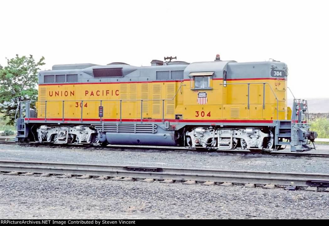
This piping is what I will be duplicating and the Z5 piping and cast brackets will be excellent. I just need to cut they down, reconfigure and solder back together on the bkts.
-
riogrande491

- Posts: 80
- Joined: Thu Aug 09, 2012 8:50 pm
- Location: Northern Colorado
- Contact:
Re: Flat Soldering Jig
I use T pins to hold items on a scrap piece of Micore before soldering with a resistance iron. Micore won't burn as it is a cementacious product so it should even be safe with a torch.
Bob
A&O Historical Society
A&O Historical Society
Re: Flat Soldering Jig
Thanks Bob, that's what I was looking for. I've seen in it use decades ago.....I just never knew what it was. Might have even seen it on one of your photo journals. 
Return to “O-Gauge, 2-Rail, Model Railroading”
Who is online
Users browsing this forum: Bing [Bot] and 98 guests