Easy? Trivial.
A copyright violation? Unquestionably.
Machine Shop / Locomotive Drive Work
-
bob turner
- Posts: 12858
- Joined: Sat Jan 13, 2007 7:57 pm
-
ScaleCraft

- Posts: 6463
- Joined: Thu Jan 26, 2012 10:15 pm
- Location: Floe Ice, Auntarctica
Re: Machine Shop / Locomotive Drive Work
bob turner wrote:Easy? Trivial.
A copyright violation? Unquestionably.
I won't argue. But posting a link, and NOT hotlinking, always was okay. Something changed?
Dave....collector, restorer, and operator of the finest doorstops
-
bob turner
- Posts: 12858
- Joined: Sat Jan 13, 2007 7:57 pm
Re: Machine Shop / Locomotive Drive Work
No. Links are ok.
-
ScaleCraft
- Posts: 6463
- Joined: Thu Jan 26, 2012 10:15 pm
- Location: Floe Ice, Auntarctica
Re: Machine Shop / Locomotive Drive Work
's what I thought. Ran into an issue many years ago on one forum.
I would post a link, and the software they were using for the forum automatically parsed the link to a picture.
I would post a link, and the software they were using for the forum automatically parsed the link to a picture.
Dave....collector, restorer, and operator of the finest doorstops
-
R.K. Maroon

- Posts: 2939
- Joined: Tue Feb 22, 2011 9:20 pm
Re: Machine Shop / Locomotive Drive Work
FINALLY -- at last, I have the 4-4-2 operable. The new motor bracket worked out very well, but I couldn't find a sweet spot on the amount engagement of the ball and socket that was both smooth and reliable (it was one or the other). I reviewed Bob's notes on setup and came up with a slightly different approach, which was to leave the universal joint in place and replace the ball-and-socket with a section of rubber tubing. I can report that the reputation of Toyota vacuum hose is intact -- it was just what was needed. Here is a photo from the first test run of this setup:

A short video of the locomotive in action can be seen here:
https://www.dropbox.com/s/gz0on5rr83r15xi/Test%20Run.mp4?raw=1
One thing I noticed from the video: The short wheelbase of the 4-4-2 shows the irregularities in the track just as well as the big engines I normally use to test trackwork. Our portable layout has adjustments to level the track across the joints, but it's a tedious operation so we don't do it that often. Looks like we'd better get busy.
As to the 4-4-2, the only thing left to do now is to replace the couplers that were broken in shipping and do a little touch-up. I will post a video of the locomotive in revenue service when ready.
Jim
Slow progress is better than no progress
-
bob turner
- Posts: 12858
- Joined: Sat Jan 13, 2007 7:57 pm
Re: Machine Shop / Locomotive Drive Work
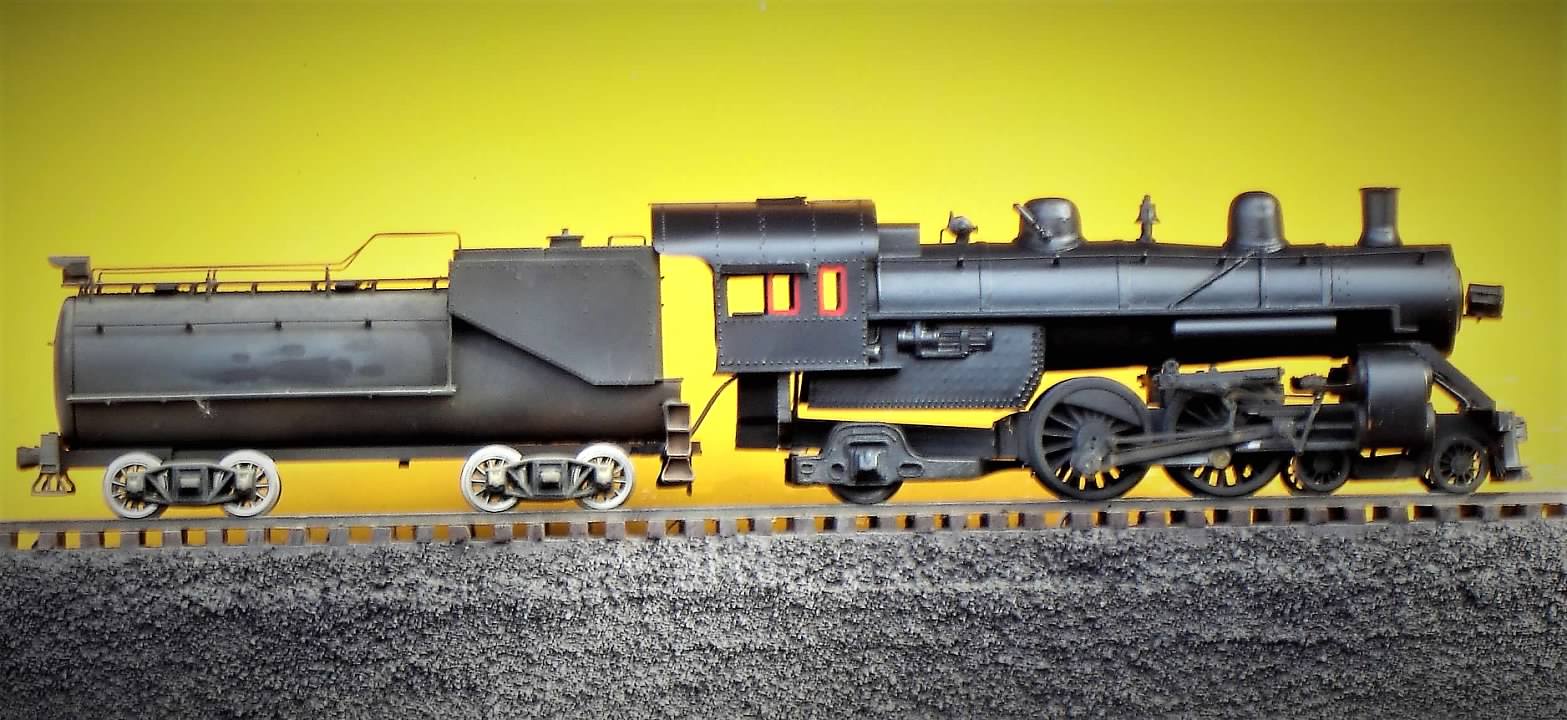
This is far from finished, but I am stopping here. Needs pilot work, maybe some cab straightening, injectors and check valves, better air cooling pipes, and some distant day, gears and motor. Thanks to Maroon for inspiring the work - I think it looks better than a regular AN Atlantic.
-
R.K. Maroon
- Posts: 2939
- Joined: Tue Feb 22, 2011 9:20 pm
Re: Machine Shop / Locomotive Drive Work
Bob, I do like the lines on that Atlantic. It doesn't look far from finished to me (or at least not so far that I would consider stopping at this point). But I am all to familiar with the 80-20 rule and am guessing there is indeed a lot of work to get all the details on and otherwise finish it up. Still -- I think its quite a beauty, and the workmanship speaks for itself.
Jim
Jim
Slow progress is better than no progress

Re: Machine Shop / Locomotive Drive Work
I think he had me with the tender with the spoked trucks.
Nice model.
Bob, I know you dislike finishing your stuff but if you ever want someone to decal, glaze and otherwise finish these jewels let me know.
Nice model.
Bob, I know you dislike finishing your stuff but if you ever want someone to decal, glaze and otherwise finish these jewels let me know.
Litigation Crisis Consultant- remediating legal-media issues; mitigating federal, state and local investigations, court orders etc. Your serial felony history, contractual defaults, bankruptcies no big deal.
contact morbo@getoffthehook.com
contact morbo@getoffthehook.com
-
bob turner
- Posts: 12858
- Joined: Sat Jan 13, 2007 7:57 pm
Re: Machine Shop / Locomotive Drive Work
Should do that with the CG E7.
But this one needs the basics - an ashpan, injectors and check valves, a new pilot step arrangement, class lamps, number boards - only then do we get gloss black, decals, dullcoat etc.
Oh - and a new smokebox front with a bit more classy headlight. Lot of work. SE-4 is back at the workbench, and I will finish that one. And, it runs!
-
Rufus T. Firefly
- Posts: 41330
- Joined: Wed May 16, 2007 6:52 am
- Location: Departed from this forum
Re: Machine Shop / Locomotive Drive Work
De Bruin wrote:I think he had me with the tender with the spoked trucks.
Yes. It's a visual that changes everything. Been on my to do list for my CVRR tenders for years.....
Conservatism: The intense fear that somewhere, somehow, someone you think is inferior is being treated as your equal.
-
R.K. Maroon
- Posts: 2939
- Joined: Tue Feb 22, 2011 9:20 pm
Re: Machine Shop / Locomotive Drive Work
I am restoring the chassis and drives of a Max Gray AB pair of FM Erie-Builts. Here is the A-unit:

The B-unit is similar. These units had all the problems of old units that have been sitting for a long time with no regular maintenance, such as hardened grease in the gearboxes and rotted rubber motor grommets. Some parts were also missing, such as journal retainers and one drive shaft. Here is an underside of the A unit:

Note the center gear tower. A drive shaft connects the lower shaft of this tower to each of the two trucks. It turns out of the four drive shafts between the two units, only one was both an original factory item and in good shape -- One was missing (see photo on left), one was factory but damaged, the other was a poorly built replacement.
I decided to fabricate all new drive shafts. This would not be much of a challenge, but the drive shafts have to be electrically insulated. The original shaft is shown here at the top:

The easy solution would have been to use the PSC driveshaft at the bottom, but this all-metal item did not provide the needed electrical isolation (and I only had one). My solution is shown in the middle. I am keeping the ball-and-socket joint at one end. A CLW Delrin universal joint goes at the other end, providing the needed insulation. I have salvaged four of the horned-ball pieces from the original driveshafts, which I will solder to the brass drive shaft shown. This is a fun little lathe part:

The only trick now is to match the original length of the drive shaft. I have purposely made the new shafts longer than they need to be:

Well, ok -- a lot longer than needed. I will wait until the chassis is reassembled, trim the length to fit, and then solder in the horned-balls. These drive shafts are an easy-enough project but there are still a lot of steps to get to a happy end. I am not sure whether it's best to put the universal at the gear tower and the ball-and-socket at the truck, or vice-versa. It's an important decision, as the universal is pinned and the ball-and-socket has a set screw. I may bench test with metal screw-on universals (and direct wires to the motors) before committing to drilling holes for the pins. Opinions is this regard are encouraged.
Jim
The B-unit is similar. These units had all the problems of old units that have been sitting for a long time with no regular maintenance, such as hardened grease in the gearboxes and rotted rubber motor grommets. Some parts were also missing, such as journal retainers and one drive shaft. Here is an underside of the A unit:
Note the center gear tower. A drive shaft connects the lower shaft of this tower to each of the two trucks. It turns out of the four drive shafts between the two units, only one was both an original factory item and in good shape -- One was missing (see photo on left), one was factory but damaged, the other was a poorly built replacement.
I decided to fabricate all new drive shafts. This would not be much of a challenge, but the drive shafts have to be electrically insulated. The original shaft is shown here at the top:
The easy solution would have been to use the PSC driveshaft at the bottom, but this all-metal item did not provide the needed electrical isolation (and I only had one). My solution is shown in the middle. I am keeping the ball-and-socket joint at one end. A CLW Delrin universal joint goes at the other end, providing the needed insulation. I have salvaged four of the horned-ball pieces from the original driveshafts, which I will solder to the brass drive shaft shown. This is a fun little lathe part:
The only trick now is to match the original length of the drive shaft. I have purposely made the new shafts longer than they need to be:
Well, ok -- a lot longer than needed. I will wait until the chassis is reassembled, trim the length to fit, and then solder in the horned-balls. These drive shafts are an easy-enough project but there are still a lot of steps to get to a happy end. I am not sure whether it's best to put the universal at the gear tower and the ball-and-socket at the truck, or vice-versa. It's an important decision, as the universal is pinned and the ball-and-socket has a set screw. I may bench test with metal screw-on universals (and direct wires to the motors) before committing to drilling holes for the pins. Opinions is this regard are encouraged.
Jim
Slow progress is better than no progress
-
R.K. Maroon
- Posts: 2939
- Joined: Tue Feb 22, 2011 9:20 pm
Re: Machine Shop / Locomotive Drive Work
Here is more on the new drive shafts for the Max Gray Erie-Builts. The next step was to drill a hole in the power-truck worm shafts. This can be tricky, but by good chance John Wubble of All Nation has introduced a 3D-printed version of a drill guide tool that came with the All Nation legacy inventory:
https://allnationline.com/WP/?product=all-nation-line-pittman-motor-drill-die-tool-pn9t
The bad news is that it is priced at $90, which seemed a lot for a chunk of filament-printed plastic. But, as I do a lot of drive work, I decided to order it. Things did not go well at first, but after some trial-and-error, I found a way to use the tool successfully. Here is the setup:

I have sent feedback to John and will be interested to see what he says. After I hear back from him, I will share more details about this tool.
Having the holes drilled allowed mounting of the universal joints:

I could now do a check fit to the chassis and drive tower to determine the optimum length of the drive shafts. As suspected, the front and rear driveshafts needed to be different lengths. Here is a double-check of the fit after the length has been trimmed:

The next step was to drill the drive shaft for the other side of the universal joint. The brass rod drills easily, so I clamped a v-block to the drill press and held the piece with a finger:

I get the feeling that drilling the rod without clamping it is one of those "it works until it doesn't" things, but so far, so good.
The next step is to solder in the dog-bones. More later.
Jim
https://allnationline.com/WP/?product=all-nation-line-pittman-motor-drill-die-tool-pn9t
The bad news is that it is priced at $90, which seemed a lot for a chunk of filament-printed plastic. But, as I do a lot of drive work, I decided to order it. Things did not go well at first, but after some trial-and-error, I found a way to use the tool successfully. Here is the setup:
I have sent feedback to John and will be interested to see what he says. After I hear back from him, I will share more details about this tool.
Having the holes drilled allowed mounting of the universal joints:
I could now do a check fit to the chassis and drive tower to determine the optimum length of the drive shafts. As suspected, the front and rear driveshafts needed to be different lengths. Here is a double-check of the fit after the length has been trimmed:
The next step was to drill the drive shaft for the other side of the universal joint. The brass rod drills easily, so I clamped a v-block to the drill press and held the piece with a finger:
I get the feeling that drilling the rod without clamping it is one of those "it works until it doesn't" things, but so far, so good.
The next step is to solder in the dog-bones. More later.
Jim
Slow progress is better than no progress
-
R.K. Maroon
- Posts: 2939
- Joined: Tue Feb 22, 2011 9:20 pm
Re: Machine Shop / Locomotive Drive Work
I am near the finish line with the chassis restoration of the Max Gray FM Erie-Builts. Soldering the dog-bones in place was straightforward. It's a task better suited for a torch than a resistance unit or a soldering iron -- very similar in fact to sweating copper water pipe. Here are a few photos showing the A-unit chassis during final assembly:


The axle gearboxes look like the ubiquitous GMC/All Nation variety -- well, they are clearly a knockoff of there of -- but they have a slightly different gear ratio (one extra tooth on the gear, as I recall). I have a pair of Max Gray GP7s with the same setup and have seen other examples. These predate the KTM die-cast enclosed gearboxes typically found on US Hobbies diesels.
The B-unit is also powered. Its chassis will be ready for assembly tomorrow. The last step on the chassis work will be to jumper these units together for better operational reliability.
Jim
Slow progress is better than no progress
-
bob turner
- Posts: 12858
- Joined: Sat Jan 13, 2007 7:57 pm
Re: Machine Shop / Locomotive Drive Work
One thing to look out for - at the end of Bill Pope's tenure, he hired some relatively unskilled young assemblers.
They got less than perfect press fits and rivet headings. If an axle bearing or a steel side piece works loose, the first indication will be a destroyed axle gear.
I note that here the drivers are rim-insulated, so they are old enough that all swaging and riveting is up to the original high quality, but beware of gearboxes delivered near the end of production.
On the drilling jig - I make my own out of brass bar. If you use care, you will find that a smaller drill will find the exact diametrical opposite spot to exit a drilled hole for your shaft. Then you merely invert the jig using the accurate (orthogonal) hole, and clamp and drill. Works. Happy to make one and ship it for $89.99.
I do have a rivet swager gimmick around here - happy to lend it out if I can find it.
-
R.K. Maroon
- Posts: 2939
- Joined: Tue Feb 22, 2011 9:20 pm
Re: Machine Shop / Locomotive Drive Work
I finished the restoration of the two chassis for the Max Gray Erie-Builts today. Our layout is undergoing upgrade and only a short section is operational at present, but it was enough for a short test run. You can see that I installed a jumper between the units to improve the reliability of rail contact. Doing this is faster than installing wheel wipers and is a good solution for paired units such as these:

Here is the A-unit. The electronic board is a home-built unit for a constant brightness headlight. It uses an LM344 device to provide constant current to an LED headlight. It works with an incandescent too. The white connector is the harness to the headlight, allowing disconnect of the superstructure from the chassis:

Here is the B-unit. I plan to secure the wires a little better before final assembly.

Here's a short video. I like the sound of these:
https://www.dropbox.com/s/cyk6ua588qa2944/AB%20Chassis%20Test.mp4?raw=1
The bodies go back on these and then go next to my brother's paint shop in Atlanta.
Jim
Here is the A-unit. The electronic board is a home-built unit for a constant brightness headlight. It uses an LM344 device to provide constant current to an LED headlight. It works with an incandescent too. The white connector is the harness to the headlight, allowing disconnect of the superstructure from the chassis:
Here is the B-unit. I plan to secure the wires a little better before final assembly.
Here's a short video. I like the sound of these:
https://www.dropbox.com/s/cyk6ua588qa2944/AB%20Chassis%20Test.mp4?raw=1
The bodies go back on these and then go next to my brother's paint shop in Atlanta.
Jim
Slow progress is better than no progress
Return to “O-Gauge, 2-Rail, Model Railroading”
Who is online
Users browsing this forum: No registered users and 12 guests